English
 French


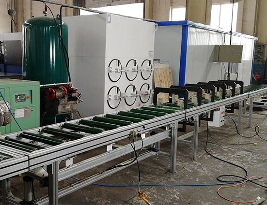
The LT HQY255-125 is a busduct and busway bridge housing extrusion pressing and clamping machine used for the riveting assembly of busbar rows from 91...
The LT HQY255-125 is a busduct and busway bridge housing extrusion pressing and clamping machine used for the riveting assembly of busbar rows from 91 to 255 mm wide and up to 125 mm high. It prepares the bridge for riveting before the joint is closed, working across the 125 × 255 mm and 125 × 91 mm busbar bridge specifications. The upper pressing device is built from bolts with an 8 mm steel plate as a single unit and is guided by a guide block, which keeps the pressing face square to the housing. In UK busway assembly this is the station that sets the joint geometry before the rivets go in.
Test conditions: Extrusion pressing and clamping of busduct/busway bridge housings ahead of riveting, across 91–255 mm width and 125 mm height busbar rows.
Measured values: Works across 125 × 255 mm and 125 × 91 mm bridge specifications; upper pressing device formed from bolts with 8 mm steel plate as a single unit guided by a guide block; pneumatic blocks pre-installed on the device; documentation covers safety warning, machine principle, performance parameters, pneumatic schematic, accessory table, wiring table and safe operating procedures.
Benchmark: Pressed and clamped before riveting against riveting a loose bridge: the joint geometry is set square first, so the rivets only have to hold the joint rather than pull it into alignment.
HQY255-125 Busduct Busway Bridge Housing Extrusion Pressing Clamping Machine
Features:
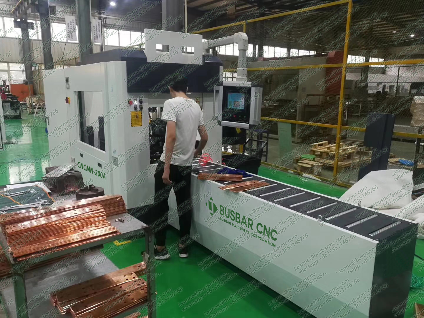
1. Use and requirements:The busbar press is equipped with three parts: riveting table, prefabricated table and discharge table. It is used for riveting assembly of busbar row of 91 ~ 255mm width and height of 125mm. After the busbar row is installed, push the riveting table and press Will be targeted after the compression to facilitate the artificial riveting.
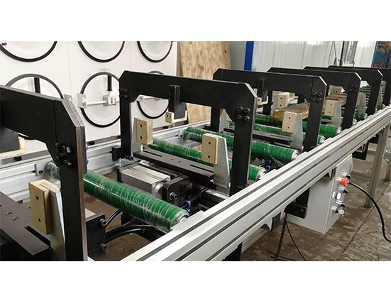
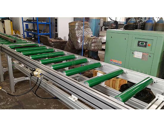
2. With relay control, pneumatic clamping, no power roller with integral installation, roller surface covered with polyurethane, to prevent scratching the bridge. The frame steel beam is formed by bending the steel plate and is supported by the steel pipe of the square pipe, which can be adjusted according to the need, the rack surface spray (gray). The upper pressing device is made of bolts with 8mm steel plate as a whole and guided by guide block. Work will be pre-installed bridge to the appropriate position, depress the foot switch, the top material device to lift the bridge from the roller in place after the remain intact, both sides of the clamping device action clamping the bridge, the last pressure Tight device action will be copper compacted. After the completion of artificial riveting, step down the foot switch, the pressure on the rise, both sides of the pressure release, the top material device down the bridge to fall back to the roller surface, the bridge pushed out to the discharge station for follow-up operation.
Bridge processing requirements:
1, the bus press for 125 × 255mm and 125X91mm between the specifications of the bridge, before the riveting clamping operation.
2, Pre-installed part of the pneumatic block on the device.
Technical support:
Busbar press machine instructions:
Including safety warning, machine principle, performance parameters, pneumatic schematic diagram, accessory table, wiring table, safe operating procedures.