English
 French


Busbar Punching Guide — Hole Accuracy, Dies & Positioning
Define accuracy before you set up
| Drawing control | Why it matters |
|---|---|
| Datum | All positions are measured from here |
| Hole centre pitch | Kit fit to breakers and terminals |
| Edge distance | Die strength and standard compliance |
| Positional tolerance | Pass or fail criterion for the FAT |
| Profile (round, oblong, rectangular) | Die selection |
Verify finished holes from the drawing datum on multiple consecutive parts. A single measured hole proves nothing about the machine; a run of ten proves the setup.
Dies, clearance and turret practice
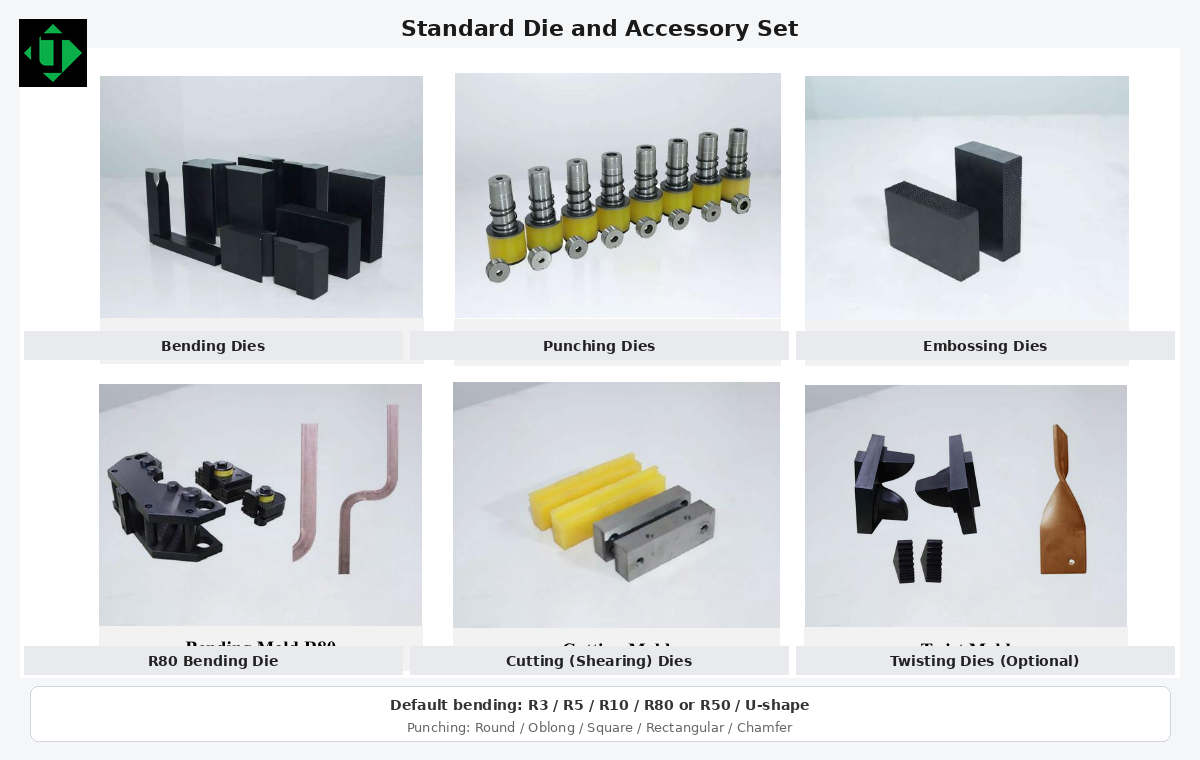
Select dies for the actual material, temper, thickness and profile.
Confirm punch-to-die clearance, and re-check it after every copper to aluminium switch.
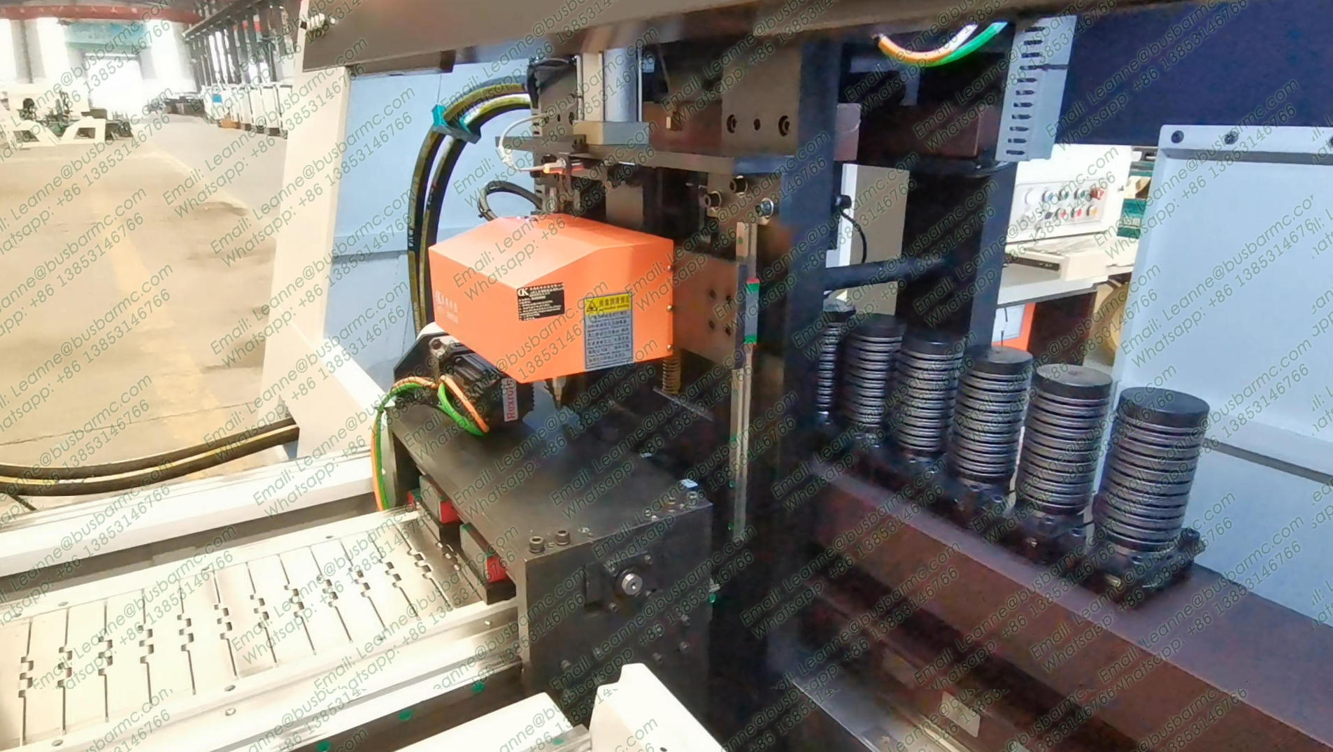
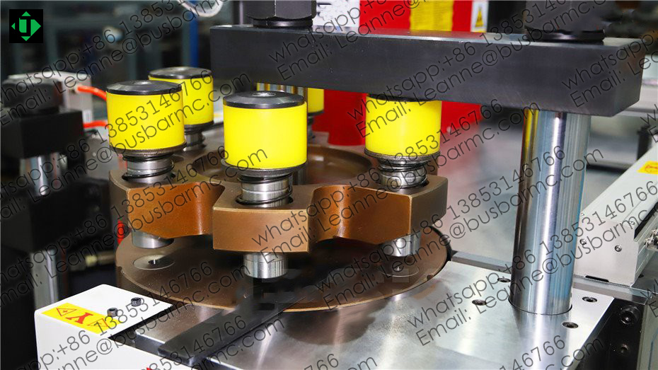
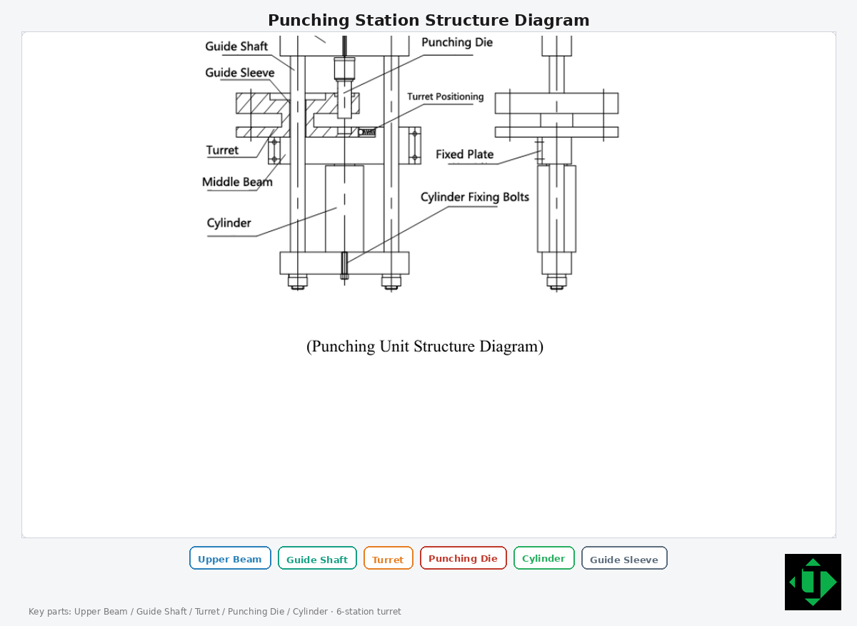
Turret designs keep several dies centred so changeover is a rotation rather than a rebuild.
Typical starter families include round Ø7, 9, 11, 13 and 17 mm, and oblong 11 × 15, 13 × 18 and 17 × 21 mm — confirm the exact list on the order.
Published punching ranges on the LT range are Φ4.3–25, Φ4.3–30 and Φ4.3–34 mm across the 303, 503 and 803 classes.
After each die change, inspect burr, deformation and edge quality before releasing the batch. A die that is seated 0.2 mm off centre will pass a visual check and fail a bolt-up check three stations later.
Positioning: manual versus servo or CNC
| Method | Helps when… | Still manual? |
|---|---|---|
| Scale or stop | Low mix | Yes, positioning and clamping |
| Servo axis | Recurring coordinates | Loading and clamping often yes |
| CNC program | Multi-hole kits | Tool change and inspection |
Hydraulic punch force and CNC positioning coexist on the same machine. Compare labour content and repeatability, not marketing slogans about automation.
Model capacity for punching
| Specification | 303U-3-C | 503U-3-C | 803U-3-C |
|---|---|---|---|
| Nominal force | 300 kN | 500 kN | 800 kN |
| Punching diameter | Φ4.3–25 mm | Φ4.3–30 mm | Φ4.3–34 mm |
| Max. thickness × width | 12 × 150 mm | 16 × 200 mm | 20 × 250 mm |
| Max. horizontal bend | 150 × 12 mm | 200 × 16 mm | 250 × 20 mm |
| Max. vertical bend | 10 × 100 mm | 12 × 120 mm | 12 × 120 mm |
| Motor power | 3 × 4 kW | 3 × 5.5 kW | 3 × 5.5 kW |
| Bend accuracy / repeat | ±1° / ±0.5° | ±1° / ±0.5° | ±1° / ±0.5° |
| Approx. mass | 1,400 kg | 1,700 kg | 2,100 kg |
FAT checks for punched busbars
Hole diameters and oblong dimensions against the drawing.
Positions measured from datum on the first, middle and last part.
Minimum edge distances.
Burr height and surface marks.
Deformation around dense hole fields.
Dense hole fields are where soft material shows its weakness: the ligament between holes deforms and the bar bows. If that appears at the FAT, the answer is usually a clearance or sequencing change rather than a bigger machine.
Common causes of hole position error
| Symptom | Likely cause | Correction |
|---|---|---|
| Consistent offset in one direction | Datum or stop reference error | Re-establish datum on first article |
| Random scatter along the bar | Bar not held flat, or stop slip | Support and clamp review |
| Hole out of round | Clearance too large or die worn | Die inspection and replacement |
| Burr on one side only | Die misalignment | Re-seat and align the punch |
Frequently asked questions
What decides busbar hole accuracy?
Datum discipline, positioning method, die condition and stable material — not a single brochure micron claim.
Can the same turret punch both copper and aluminium?
Often yes with the correct clearance and force margin. Re-qualify the setup after every material change.
What is the difference between round and oblong dies?
Oblongs need matching die pairs and orientation control. List them explicitly in the RFQ so the die package is quoted correctly.
Where does punching sit on a 3-in-1 machine?
It is an independent station beside shear and bend. Three pump groups allow parallel work when staffed.
How do I stop burrs on punched copper busbar?
Check punch-to-die clearance first, then die sharpness and alignment. Burrs that appear on one side only usually indicate misalignment rather than a tonnage problem.